
JP Instruments
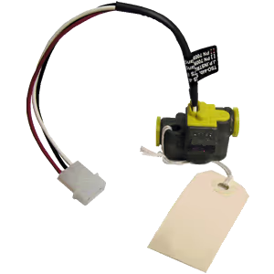
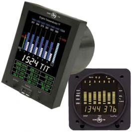
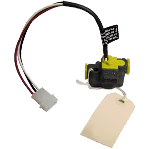
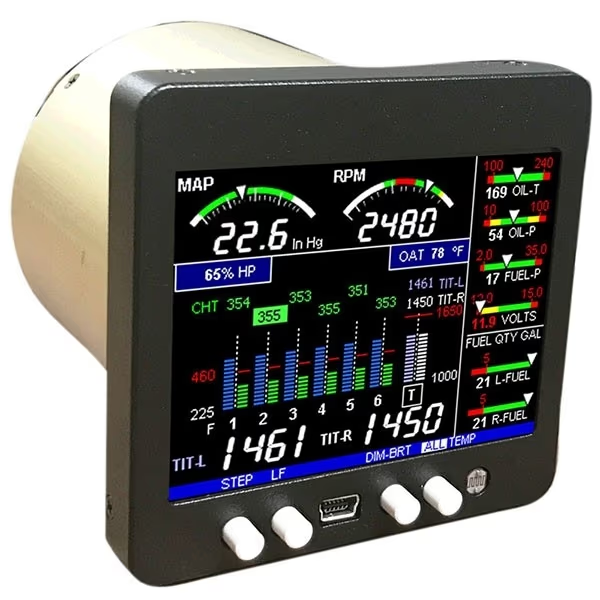
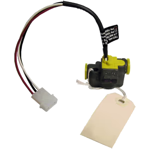
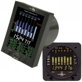
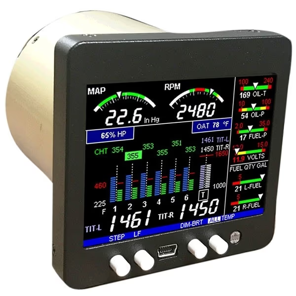
Fuel Flow option for EDM-760/790, With (2) 231 transducers, Harness included
Fuel Flow option for EDM-760/790 with two 231 transducers and harness
No reviews yetSKU JPI FF-231-760-790
$1,050.00$1,250.00Save 16%
In stock — ready to ship
- Ships in 1–2 days
- Genuine parts
- Pilot support
- 30-day returns
Fuel Flow option for JP Instruments EDM-760/790 including two 231 fuel flow transducers and a harness.
Important Information
- Most JP Instruments EDM options can be added at any time; EDM-760/700 models are exceptions.
- Mount transducer horizontal with the three wires up; failure to do so may result in premature failure and refer to Report #503.
- Do not bend the line within 6 inches of the transducer; do not use aluminum fittings.
- Carbureted engine installation: install before the carburetor; if transducer is higher than carburetor, add an anti-siphon loop that peaks higher than the transducer.
- Injected engine installation guidance and vapor-return exception.
- Do not mount between the electric boost pump and the mechanical pump (not recommended).
- Do not hard mount the transducer to the engine; vibration may damage internal parts or cause erratic readings.
- Tighten fittings to no more than 15 ft lb (180 in lbs) or two full turns past hand tight.
- Do not use Teflon tape or any thread sealant; doing so will void the transducer warranty.
- Be sure there is no bend in the line closer than 6 inches before or after the transducer. Do not use aluminum fittings when installing the fuel flow transducer.
- Mounting the transducer between the electric boost pump and the mechanical pump is not recommended.
- ** Do not use Teflon tape or thread sealant compound of any kind – this will void transducer warranty.**
- Measures flows of hydrocarbon fuels and similar light transmitting, non-corrosive liquids.
- Gives repeatable signals on gasoline across a wide flow range down to low flows.
- Transducer bearing system rated for continuous operation at the upper end of the flow range.
- Produces a current pulse signal via an opto-electronic pickup with a preamplifier.
- Low pressure drop compared to other turbine flow transducers.
Electrical & RF
- Operating Voltage
- 12 to 15 VDC between RED (+) wire and BLACK (-) wire.
- Output Current
- 30 to 50 mA at 12 VDC.
Construction
- Connection Type
- Open collector transistor output on WHITE wire; sensor will pull-down to 1.0 volt with 10-15k ohm pull-up resistor installed.
- Pressure
- Pressure drop (201) 1.2 psi at 30 GPH, 4.8 psi at 60 GPH; Pressure drop (231) 0.31 psi at 30 GPH, 2.8 psi at 60 GPH; Pressure drop (H) 0.23 psi at 30 GPH, 0.8 psi at 60 GPH; Working pressure (201, 231) 200 psi, (H) 1500 psi; Maximum burst pressure 2000 psi.
In the box
- Included Components
- With (2) 231 transducers, Harness included
General
- Flow Rate
- Range (201) 0.6 to 60 GPH, (231) 3 to 90 GPH, (H) 3 to 120 GPH
You may also like
JP Instruments
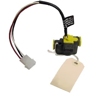
Fuel Flow option for EDM-760/790, With (2) 201 transducers, Harness included
In stock
$1,050.00$1,250.00
JP Instruments
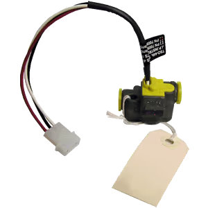
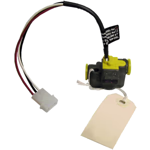
Fuel Flow option for EDM-760/790, Without transducers, Harness included
In stock
$875.00
Customer reviews
—/ 5
No reviews yet
5★
0
4★
0
3★
0
2★
0
1★
0
Loading reviews…