
JP Instruments
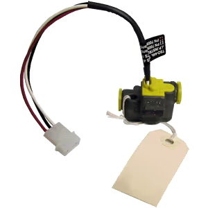
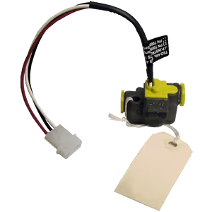
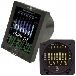
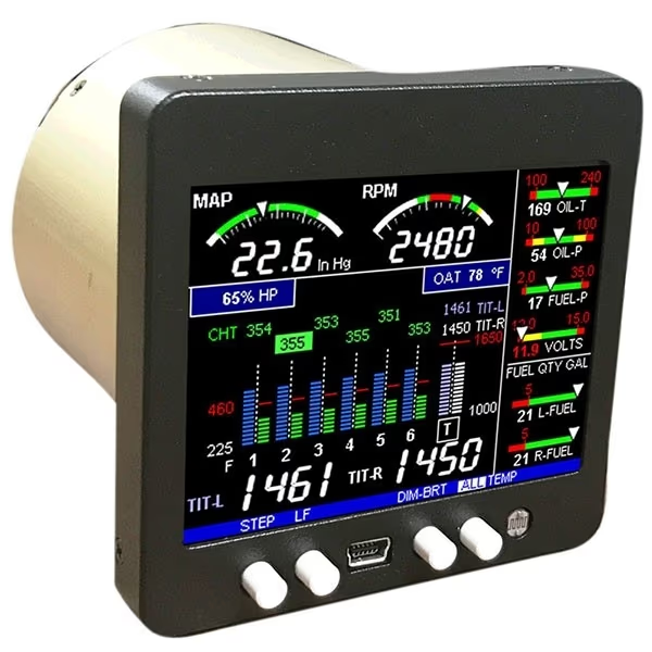
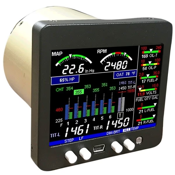
Fuel Flow option for EDM-760/790, With (2) 201 transducers, Harness included
Fuel flow option kit for JPI EDM-760/790 with two 201 transducers and harness.
No reviews yetSKU JPI FF-201-760-790
$1,050.00$1,250.00Save 16%
In stock — ready to ship
- Ships in 1–2 days
- Genuine parts
- Pilot support
- 30-day returns
Fuel Flow option kit FF-201-760-790 for JP Instruments EDM-760/790 including two 201 fuel flow transducers and an installation harness.
Important Information
- Most JP Instruments EDM options can be added at any time for singles and twins.
- You do not have to send the instrument back, everything is plug and play with the exception of EDM-760/700 Models.
- Make sure the transducer is Horizontal with the three wires up. Failure to do this will result in premature failure. Please refer to Report #503 that came with your EDM with Fuel Flow.
- Mount in a horizontal position with the wires up, as this ensures that the rotor is in proper orientation to the flow of fuel just as it was calibrated.
- Be sure there is no bend in the line closer than 6 inches before or after the transducer.
- Do not use aluminum fittings when installing the fuel flow transducer.
- For carbureted engines, before the carburetor. If the transducer is higher than the carburetor, put an anti-siphon loop in the line that peaks higher than the transducer (see installation manual, but the diagram shows the transducer on its side, rather than the correct position which is with the wires coming off the top).
- For injected engines, between the engine fuel pump and the servo regulator. For injected engines with vapor return lines (rare), between the servo regulator and the flow divider (spider).
- Mounting the transducer between the electric boost pump and the mechanical pump is not recommended.
- Do not hard mount the transducer to the engine. Vibration may damage the internal parts of the transducer or cause erratic readings.
- Tighten fittings not more than 15 ft lb = 180 in lbs., or two full turns past hand tight.
- ** Do not use Teflon tape or thread sealant compound of any kind – this will void transducer warranty.**
- The transducers produce a current pulse signal from an opto-electronic pickup with a preamplifier.
- The transducers give repeatable signals on gasoline across a 100 to 1 flow range down to 0.3 GPH.
- Pressure drops are very low compared to other turbine flow transducers.
- The transducer bearing system is rated for continuous operation at the upper end of the flow range.
- Linearity 1%
- K-factor (201) ~ 29.00, (231) ~19.50, (H) ~48.00
- Temperature range, operating -55°C to 70°C
- Temperature range, non-operating (201, 231) -65°C to 125°C, (H) -65°C to 100°C
Part numbers
- Manufacturer Part Number
- JPI FF-201-760-790
Size & weight
- Size
- Fuel ports (201, 231) 1/4 Female NPT (H) AN816-8-8
Electrical & RF
- Operating Voltage
- 12 to 15 VDC between RED (+) wire and BLACK (-) wire.
- Output Current
- 30 to 50 mA at 12 VDC.
Construction
- Connection Type
- Open collector transistor output on WHITE wire.
- Pressure
- Pressure drop (201) 1.2 psi at 30 GPH, 4.8 psi at 60 GPH; Pressure drop (231) 0.31 psi at 30 GPH, 2.8 psi at 60 GPH; Pressure drop (H) 0.23 psi at 30 GPH, 0.8 psi at 60 GPH; Working pressure (201, 231) 200 psi, (H) 1500 psi; Maximum burst pressure 2000 psi
In the box
- Included Components
- With (2) 201 transducers, Harness included
General
- Output Voltage
- Sensor will pull-down to 1.0 volt with 10-15k ohm pull-up resistor installed.
- Flow Rate
- Range (201) 0.6 to 60 GPH, (231) 3 to 90 GPH, (H) 3 to 120 GPH
You may also like
JP Instruments
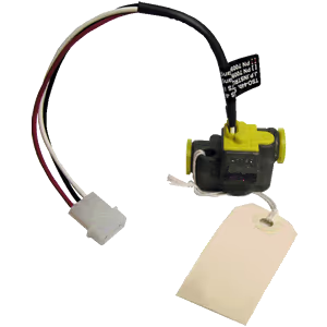
Fuel Flow option for EDM-760/790, With (2) 231 transducers, Harness included
In stock
$1,050.00$1,250.00
JP Instruments
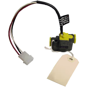
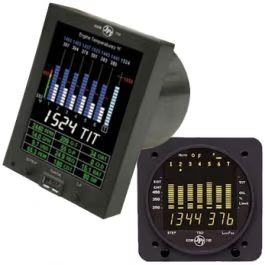
Fuel Flow option for EDM-760/790, Without transducers, Harness included
In stock
$875.00
Customer reviews
—/ 5
No reviews yet
5★
0
4★
0
3★
0
2★
0
1★
0
Loading reviews…